
1 Overview
Oil and gas boiler power generation has a history of more than 60 years in China. The boilers built in Northeast my country at that time are still operating safely today. The currently developed oil-fired boilers and gas-fired boilers add energy-saving, environmentally friendly and other technologies to the original gas generators, making them efficient, energy-saving, safe and environmentally friendly technologies. The economic operation of boilers is an issue that urgently needs attention. It not only involves the individual economy, but also is of great significance to saving energy and achieving sustainable and coordinated development in the future when energy is increasingly scarce.
The UW500 distributed control system is a new generation distributed control system jointly developed by Hangzhou Youwen and the National Engineering Research Center for Industrial Automation of Zhejiang University. It is a new generation distributed control system launched through continuous analysis and summary, development and innovation, testing improvement and assessment. This system can significantly improve the automation level of monitoring and improve the economical and reliable operation of the boiler.
2. Process introduction
The process of power generation is a process of energy conversion: fuel chemical energy steam thermal energy mechanical energy electrical energy. To put it simply, it uses fuel (gas) to generate heat and heat water to form high-temperature and high-pressure superheated steam, which drives the turbine to rotate and the generator rotor (electromagnetic field) to rotate. The stator coil cuts the magnetic lines of force to emit electric energy, and then uses the step-up transformer to rise to The system voltage is connected to the grid and transmits electric energy to the outside.
The main equipment systems of gas-fired power generation include: fuel supply system, water supply system, steam system, cooling system, electrical system and other auxiliary processing equipment.
Its power generation system mainly consists of combustion system (with boiler as the core), steam and water system (mainly composed of various pumps, feed water heaters, condensers, pipelines, water walls, etc.), electrical system (with turbine generator, main transformer etc.), control system, etc. The first two generate high-temperature and high-pressure steam; the electrical system realizes the transformation from thermal energy and mechanical energy to electrical energy; and the control system ensures the safe, reasonable and economical operation of each system.
3. Control strategy
The automation function of the distributed control system boiler unit includes data acquisition function (DAS), analog control function (MCS), turbine shutdown protection (ETS), sequence control function (SCS), boiler main fuel cutoff protection (MFT) and information Management and other functions.
1. Gas fuel control system
In general boiler combustion system control, the main controlled parameter is main steam pressure or load. The control of main steam pressure and load parameters is achieved by adjusting the amount of gas entering the boiler. The fuel quantity control system of the boiler is based on controlling the outlet steam pressure of the boiler, and the main steam flow rate of the boiler is used as feedforward.
The combustion system of the blast furnace gas generating unit can maintain the boiler operating at a fuel load of 25% to 110% according to the amount of gas without stopping the furnace as much as possible through the unit. The change in the opening of the steam turbine inlet valve will cause the pressure parameters of the main steam, and the pressure of the main steam can be stabilized by adjusting the fuel through feedback control. Therefore, this system first ensures the blast furnace gas inlet pressure, controls the blast furnace gas inlet pressure by adjusting the opening of the blast furnace gas inlet valve, and controls the fuel when the gas pressure is guaranteed.
2. Air supply volume control system (smoke oxygen content control system)
The air supply control must not only ensure the safe combustion of the boiler, but also ensure the economic benefits of the boiler. The air supply control system ultimately marks the safety and economy of its combustion conditions by ensuring the optimal oxygen volume at the furnace outlet.
The air supply control system is mainly used to adjust the air distribution volume of the blast furnace gas, and then the oxygen volume correction circuit is cascade connected to the air supply volume control loop.
3. Induced air volume control system (furnace negative pressure control system)
According to the blast furnace gas power generation practice project, the induced draft control system uses the furnace negative pressure as the main control parameter, but the total air supply signal can be used as a feedforward signal.
4. Coordinated control of machines and furnaces
If the main steam pressure at the boiler outlet changes, the amount of blast furnace gas fuel will change. If the amount of blast furnace gas fuel changes, it will inevitably be displayed through changes in its pressure parameter value. Therefore, the control of the fuel system is to control the combustion state by adjusting the opening of the blast furnace gas inlet valve to control the blast furnace gas inlet pressure (rather than controlling the amount of gas fuel inlet), in conjunction with the control of the steam turbine to control the main steam of the boiler. The purpose of pressure. Therefore, on the one hand, the adjustment of the boiler load is calculated and controlled through the boiler load distribution calculation system; on the other hand, the control of the main steam main pipe pressure of the boiler is controlled by adjusting the opening of the turbine valve.
5. Main steam temperature control system
The adjustment of the main steam temperature of the boiler should be designed according to the characteristics of the boiler. Within the specified boiler operating range, when the temperature control load is reached (especially in low load and high load areas), the outlet temperature of the first-stage superheater is controlled to within the set range.
Adjustment amount: desuperheating water flow
Regulating equipment: desuperheating water regulating valve
Leading temperature signal: high temperature superheater outlet temperature
6. Water supply control (drum water level control)
Normal control should be a three-impulse control system consisting of steam flow, drum water level and feed water flow. When the load is less than 30%, single-impulse control with only drum water level is adopted. When the load is greater than 30%, it is switched to three-impulse control. A bumpless switching between single-impulse and three-impulse control should be provided, and vice versa.
The transmitter that measures the drum water level should be double redundant, preferably triple redundant, and have pressure compensation, comparison and selection.
The temperature compensated feed water flow should be added to the spray water flow to obtain the total feed water flow signal.
The steam flow measurement should be pressure and temperature compensated, and the heating main pipe flow should be added to obtain the total steam flow signal.
Adjusted quantity: drum water level
Adjustment amount: water supply flow
Auxiliary circuit input signal: feed water flow
Feedforward input signal: main steam flow
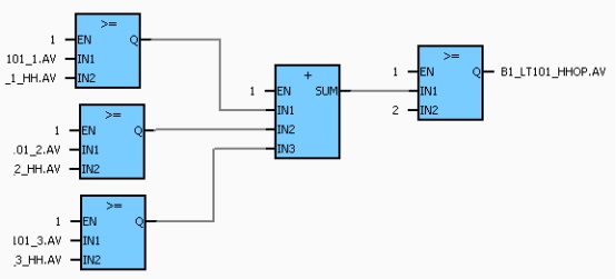
Figure 1 Steam drum liquid level protection
7. Condenser water level control system
Maintain a certain condenser water level to ensure the establishment of normal condenser vacuum. Both too high and too low water levels in the condenser may destroy the condenser vacuum. In the condenser water level control system, the deviation value between the measured value of the condenser water level and the given value is subjected to PID calculation, and the calculation result adjusts the opening of the condenser water level regulating valve to maintain a constant condenser water level.
8. Shaft seal pressure control system
At the gap between the inner partition plate and the main shaft of the steam turbine stage, as well as the place where the main shaft penetrates the outside of the cylinder, the steam cylinder will leak out or external air will leak in, which will reduce the efficiency of the steam turbine and worsen the vacuum of the unit, destroying the normal operation of the steam turbine. Therefore, a shaft seal must be used to block steam leakage and air leakage to ensure the normal operation of the steam turbine. The performance of the shaft seal is achieved by controlling the steam pressure of the shaft seal.
In the shaft seal pressure regulation system of the steam turbine generator set, the measured value of the shaft seal pressure and the given value are subjected to PID calculation, and the calculation result controls the shaft seal steam supply regulating valve to maintain the shaft seal pressure at the set value.
9. Water level control system for continuous expansion vessels
According to the water level signal of the continuous expansion vessel, the hydrophobic regulator of the continuous expansion vessel is controlled to maintain the water level of the continuous expansion vessel at the set value.
10. High pressure heater water level control system
The high-pressure heater is a heat exchange device between turbine extraction steam and main feed water. The low-pressure heater is a heat exchange device for turbine extraction steam and condensate water. Their water levels are too high, which may cause water to enter the turbine, causing an accident.
In the high-pressure heater water level adjustment system, the measured value of the water level is compared with the given value for PID operation, and the operation result controls the drain regulating valve of the high-pressure heater so that the high water level meets the operating requirements.
11. Low-pressure heater water level control system (generally not available in small units)
In the low-pressure heater water level adjustment system, the measured value of the water level is compared with the given value for PID operation, and the operation result controls the drain regulating valve of the low-pressure heater so that the low water level meets the operating requirements. In an emergency, the liquid level is controlled by the emergency water release electric door.
12. Deaerator water level control system
The purpose of maintaining the deaerator water level is to ensure the balance between boiler water supply and demand. Depending on the production process, the deaerator water level control has two adjustment methods: single impulse and three impulse. The difference between them lies in whether the chemical supplement water is continuously fed. Among them, the three-impulse adjustment method is similar to the drum water level control system. It is a single-impulse adjustment during startup and low-load operation, and it is a three-impulse adjustment during normal load. Switching between single impulse and triple impulse can be achieved manually or automatically.
When the deaerator water level reaches a high value, the deaerator water level regulator closes and the condensate recirculation valve opens. When the water level in the deaerator is too high, open the emergency water release electric door. When the turbine is out of service, the deaerator water level is adjusted by the chemical supply water valve.
13. Deaerator pressure control system
During the startup of the unit, the deaerator pressure is adjusted by opening the plant steam main pipe regulating valve to maintain the deaerator pressure set value.
Under normal load conditions, the deaerator pressure adjustment system is designed to send the deviation between the deaerator pressure measurement value and the set value to the PID for calculation. The calculation result adjusts the deaerator pressure regulating valve to control deaeration. The pressure of the device is at the set value.
4. Control engineering
UW500 distributed control system has been widely used in boiler power generation. UW500 can complete functions including data collection, analog control, furnace safety protection, electrical control, factory power public control, heating network control, etc. The system supports 32 control stations, and the system scale reaches: AIO: 16384, DIO: 32768.
The UW500 distributed control system can monitor a large number of points that need to be monitored in boiler power generation in real time. The excellent dual redundancy design makes the system more stable and reliable.
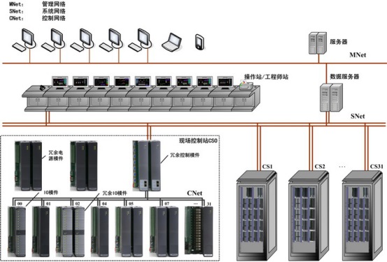
Figure 2 System Organization Diagram
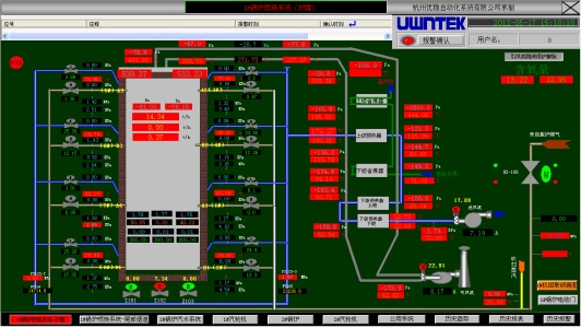
Figure 3 Boiler combustion system
5. Summary
Using the UW500 distributed control system to monitor a large number of monitoring points can greatly reduce the workload of workers, allowing a large amount of scattered data to be displayed centrally on the operating station. The stable system makes control safer and easier. The combustion of the boiler is also well controlled, which significantly improves the combustion efficiency.


