1. Overview
Petroleum is a complex mixture composed primarily of hydrocarbons. The relative molecular masses of hydrocarbons and non-hydrocarbon compounds in petroleum range from tens to thousands, and the corresponding boiling points range from normal temperature to over 500 degrees. The molecular structures are also diverse.
The petroleum refining industry produces gasoline, kerosene, diesel and other fuels and chemical industry raw materials. It is one of the most important pillar industries of the national economy. It is related to the country’s economic lifeline and energy security. It is extremely important in the national economy, national defense and social development. status and role. The world's economic powers are all powerful in the oil refining and petrochemical industries.
Petroleum cannot be directly used as fuel for the engines of automobiles, airplanes, ships and other transportation vehicles, nor can it be directly used as lubricants, solvent oils, process oils and other products. It must go through various processing processes to obtain various petroleum products that meet quality requirements. product.
The distillation of petroleum and its products is the most basic unit equipment of the oil refining unit. It is an indispensable equipment for any primary processing and secondary processing device. Crude oil can be fractionated into gasoline, kerosene and diesel fractions through atmospheric distillation. Due to the different properties of crude oil, some of these fractions can be directly used as products, while others need to be refined or processed. The atmospheric tower bottom oil is distilled under reduced pressure. Depending on the nature of the crude oil or the processing plan, the resulting fractions can be used as cracking (thermal cracking, catalytic cracking, hydrocracking, etc.) raw materials or lubricating oil raw materials, or as ethylene Crack raw materials. The bottom oil of the vacuum tower can be used as raw material for fuel oil, asphalt, coking or other residual oil processing (solvent deasphalting, residual oil catalytic cracking, residual oil hydrocracking, etc.).
For the distillation of crude oil in my country, large domestic refineries generally use atmospheric and vacuum equipment that processes 2.5 to 2.7 million tons of crude oil per year. It consists of electric desalting, initial distillation tower, atmospheric tower, vacuum tower, atmospheric heating furnace, and vacuum heating. It consists of furnace, product distillation and self-generated steam system. This device not only produces qualified gasoline, aviation kerosene, lamp kerosene, and diesel, but also produces catalytic cracking raw materials, oxidized asphalt raw materials, and residual oil; for fuel-lubricating oil refineries, it also needs to produce lubricating oil base Oil. Each refinery uses different types of crude oil, and when the type of crude oil is changed, the production plan must be changed. The process flow of the fuel-lubricating oil type atmospheric and vacuum device is: when the crude oil is sent from the tank area to the atmospheric and vacuum device, the temperature is generally about 30°C, and is sent to the heat exchanger for heat exchange through the crude oil pump. After the heat exchange, the temperature of the crude oil When it reaches 110°C, it enters the electric desalting tank for primary desalination and secondary desalination. After desalination, it heats up to about 220°C through heat exchange and enters the primary distillation tower for distillation. The crude oil at the bottom of the initial distillation tower is sent to the heat exchanger in two ways by the pump to exchange heat to about 290°C. It is sent to the atmospheric pressure heating furnace in two ways and heated to about 370°C before entering the atmospheric pressure tower. Gasoline is distilled from the top of the atmospheric tower, kerosene is distilled from the first side line (referred to as the first line), diesel is produced from the second side line (the second line is often referred to as the second line), lubricants or catalysts are produced from the third side line, and catalyst materials are produced from the fourth side line. The heavy oil at the bottom of the normal pressure tower is pumped to the normal pressure heating furnace, heated to 390°C, and then sent to the vacuum tower for vacuum distillation. Reduce the first line and the second line to produce lubricant or urging material, and reduce the third and fourth lines to produce lubricant.
2. Process introduction
1. Crude oil heat exchange system
The crude oil is sent from the oil tank to the inlet of the crude oil pump by static pressure. The filter in front of the inlet of the crude oil pump is injected with demulsifier and water that are beneficial to ensure the effect of electric desalting, and is transported by the pump into the electric desalting tank for desalination and dehydration.
Under the action of the electric field force generated by the high-voltage alternating current of 12,000 to 24,000 volts in the electric desalting tank and the action of the demulsifier, the tiny water droplets aggregate into large water droplets that settle and separate from the crude oil. Because most of the salt in the crude oil is dissolved in water, Therefore, dehydration includes desalination.
After the crude oil comes out of the electric desalting tank, the feed continues to exchange heat with the oil and enters the 31st layer of the atmospheric tower.
2. Initial distillation system
Desalting, the dehydrated crude oil exchanges heat to 215-230°C and enters the initial distillation tower. The fraction with an initial distillation point of -130°C is distilled from the top of the tower. After condensation and cooling, part of it is used for reflux at the top of the tower, and the other part is led out as reforming raw material or larger. Heavy gasoline, also known as initial top oil.
3. Normal pressure system
The crude oil from the bottom of the initial distillation tower is heated to 350-365°C in a normal pressure heating furnace and then enters the normal pressure fractionation tower. Cold reflux is driven into the top of the tower to control the temperature at the top of the tower at 90-110°C. The temperature gradually rises from the top of the tower to the feed section. Taking advantage of the different boiling point ranges of the fractions, gasoline is steamed out from the top of the tower, and kerosene, light diesel oil, and heavy diesel oil are steamed out from the first side line, the second side line, and the third side line respectively. After these side fractions are extracted into light components using superheated steam in a regular pressure stripping tower, part of the heat is recovered through heat exchange, and then cooled to a certain temperature respectively before being sent out to the device. The temperature at the bottom of the tower is about 350°C. The unvaporized heavy oil at the bottom of the tower is used as the feed oil for the vacuum tower after the light components are extracted by hot water steam. In order to make the vapor and liquid loads in each part of the tower along the height of the tower relatively uniform, and to make full use of the reflux heat, 2-3 intermediate circulation refluxes are generally inserted between the side extraction ports of the tower.
4. Pressure reduction system
The heavy oil at the bottom of the normal pressure tower is pumped into the vacuum heating furnace, heated to 390-400°C and entered into the vacuum fractionation tower. There is no product coming out of the top of the tower. After the separated non-condensable gas is condensed and cooled, the non-condensable gas is usually extracted with a two-stage steam ejector to maintain the residual pressure in the tower at 1.33-2.66kPa, so as to ensure that the oil is fully absorbed under reduced pressure. Steam out. On the tower side, lubricating oil fractions or cracked feed oils of different weights are extracted from the first and second side lines. After being stripped by gas and cooled by heat exchange, part of them can be returned to the tower for circulation and reflux, and part of them can be sent out of the device. The vacuum residue at the bottom of the tower is also blown into superheated steam to extract light components. After the extraction rate is increased, it is extracted with a pump. After heat exchange and cooling, it is discharged from the device. It can be used as self-use fuel or commercial fuel oil, or as asphalt raw material. or feedstock for propane deasphalting units to further produce heavy lubricants and asphalt.
3. Main control circuit of normal and vacuum device
Crude oil distillation is a continuous production process. An atmospheric and vacuum device that processes 2.5 million tons of crude oil per year generally has 130 to 150 control loops. Several typical control loops are introduced below.
1. Decompression furnace
The pressure of the 0.7MPa steam in the decompression furnace is controlled in separate ranges. The pressure of the 0.7MPa steam in the decompression furnace is adjusted by supplementing the 1.1MPa steam or exhausting the exhaust gas to the 0.4MPa exhaust pipe network. Using DCS to control 0.7MPa steam pressure is calculated and judged through the DCS function module to achieve split-range control of steam pressure. The 0.7MPa steam pressure detection signal is sent to the functional block regulator, which outputs a 4-12mA segment to adjust the 1.1MPa steam inlet pipe network regulating valve, and outputs a 12-20mA segment to regulate the 0.4MPa depleted gas pipe network regulating valve. This is actually based on the hard-range splitting scheme of conventional instruments to achieve split-range adjustment to maintain a stable steam pressure of 0.7MPa.
2. Reflux heat load control in the middle section of normal pressure tower and pressure reduction tower
The main function of the mid-stage reflux is to remove part of the heat load in the tower. The heat load of the mid-section reflux is the product of the temperature difference before and after the mid-section reflux is cooled by the heat exchanger, the mid-section reflux volume and the specific heat. The reflow flow rate is determined by the size of the reflow heat load in the middle section. The mid-section return flow is the middle path of the auxiliary loop, and the mid-section heat load is used to cascade the mid-section return flow to form a cascade regulating loop. The DCS calculator function block is used to calculate the temperature difference before and after cooling and to calculate the heat load. The main circuit heat load given value is given by the worker or the host computer.
3. Improve the control of heating furnace thermal efficiency
In order to improve the thermal efficiency of the heating furnace and save energy, methods such as preheating the air entering the furnace, reducing the temperature of the flue gas, and controlling the excess air coefficient have been adopted. Generally, heating furnace control uses flue gas as a heating carrier to preheat the air entering the furnace. By controlling the furnace pressure to normal, the thermal efficiency is ensured and the safe operation of the heating furnace is ensured.
4. Furnace pressure control
A micro-differential pressure transmitter is installed in the radiation to convection chamber of the normal pressure furnace and decompression furnace to measure the negative pressure of the furnace. The long-stroke actuator is used to adjust the opening of the flue gas baffle through the connecting rod. Maintain normal pressure in the furnace.
5. Control of oxygen content in flue gas
Generally, a zirconia analyzer is used to measure the oxygen content in the flue gas. The oxygen content is used to control the opening of the blower inlet baffle and the amount of air entering the furnace to achieve the best excess air coefficient and improve the thermal efficiency of the heating furnace.
6. Heating furnace outlet temperature control
There are two technical solutions for heating furnace outlet temperature control, which are switched through the switch (or soft switch) on the heating furnace process screen. One solution is to control the total outlet temperature in conjunction with the fuel oil and fuel gas flow rates, and the other solution is to balance control between the heat absorption and heat supply values of the heating furnace. Calorific value balance control requires the use of many calculator function blocks to calculate the calorific value, and at the same time use the calorific value control PID function block. Its given value is the product of the difference between the feed flow rate, specific heat, feed outlet temperature and inlet temperature of the heating furnace, that is, the endothermic value. The measured value is the calorific value of fuel oil and fuel gas, that is, the heating value. Calorific value balance control can reduce energy consumption, operate smoothly, and control the furnace outlet temperature more effectively. The development and implementation of the system fully utilizes the capabilities of the instrumentation within the DCS.
7. Normal pressure tower decoupling control
The atmospheric tower has four side lines. Changes in the extraction volume of any side line will change the internal reflux below the extraction tray, thus affecting the product quality of each side line below the side line. Generally, the normal first-line initial distillation point, the normal second-line dry point (90% dry point), and the normal third-line viscosity can be used as quality indicators in operation. In order to improve the yield of light oil, ensure the product quality of each side line, and overcome the mutual influence of each side line, decoupling control of the side lines of the atmospheric tower is adopted. Taking the constant second line as an example, the constant second line withdrawal amount can be controlled by the second line withdrawal flow, or it can be controlled by the decoupling method and switched by the process screen switch. The decoupling method uses the output of the constant second-line dry point control function block multiplied by the delay of the crude oil feed amount as the given value of the constant second-line extraction flow function block. The measured value is the sum of the side line flow rate, the normal line flow rate delay value, and the normal tower distillate oil volume delay value.
The delay function block is used during configuration, and the delay time constant is determined through experiments. This top-down dry point decoupling control method not only changes the flow rate of this side line, but also adjusts the flow rate of the next side line, thereby stabilizing the product quality of each side line. Decoupled control also adds feedforward of crude oil flow, which plays an important role in smooth operation, overcoming disturbances, and ensuring quality.
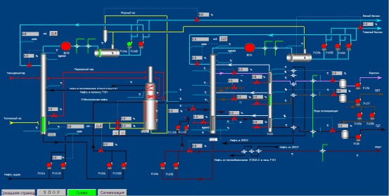
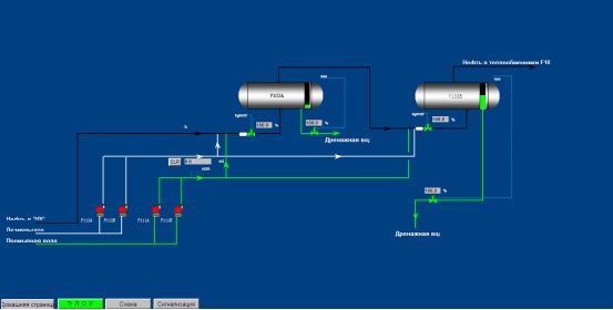
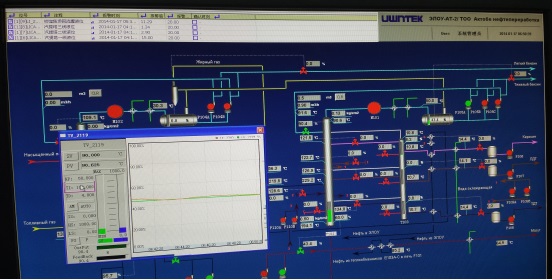
4. Project screenshots