
1. Basic composition of the heat exchange station automatic control system
The local automatic control system of the heat exchange station consists of UW2100 controller, human-machine interface (touch screen), VPN firewall, UPS, control cabinet and other equipment. It mainly realizes the collection of various data and equipment control in the heat exchange station. Under normal circumstances, the local automatic control system independently controls the automatic operation of this heat exchange station. In the case of networking, the local automatic control system of the heat exchange station can accept the instructions of the heating network monitoring system to operate. The local automatic control system of the heat exchange station can choose to communicate through the optical fiber network or GPRS wireless network, using the VPN firewall and the heating network monitoring center to form a VPN network, transmit the process data to the heating network monitoring center in real time, and remotely real-time through the heating network monitoring center Release equipment to control quality and perform process operating parameter target setting.
1.1 On-site controller of heat exchange station
The UW2100 universal intelligent controller adopts an industrial-grade high-performance embedded microcontroller and is based on the real-time multi-tasking operating system microkernel. It provides IEC61131-3FBD standard programming language, supports modbus, GPRS and other protocols, and has user programs, configuration parameters and key data. Electrical hold function.
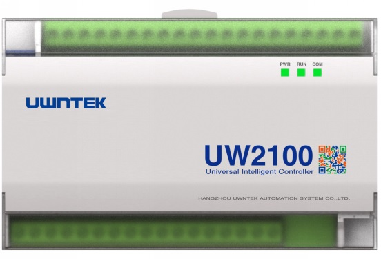
UW2100 introduction:
A. Function introduction:
1. Embedded operating system, interpret and run IEC61131-3FBD;
2. Integrated 6 module inputs, 2 module outputs, 4 digital inputs, and 4 digital outputs
3. Support 2-way RS485 communication and support master-slave MODBUS-RTU protocol;
4. Built-in real-time clock, supports bus synchronization;
5. Optional support for Ethernet (100M) or GPRS wireless communication.
B. Technical indicators:
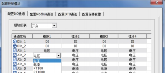
1. Analog input: supports input of various signals such as 0~10V, 0~20mA, Pt1000, Pt100, etc., with an accuracy of 0.2%F.S.;
2. Analog output: supports 0~20mA output, accuracy 0.5%F.S.;
3. Digital input: supports counter and level signal input;
4. Digital output: supports 4-channel relay output, contact capacity 1A/30VDC;
5. The minimum software running cycle is 80ms;
6. Overall dimensions: 120mm×77mm×42mm; weight: less than 250g;
7. Controller operating temperature range -20℃-70℃
The UW2100 controller can work independently and can achieve the following functions:
aParameter collection, processing (including digital operations, logical operations, flow accumulation, etc.) and display functions;
b Independently complete on-site closed-loop control and internal interlocking control functions;
c Complete on-site monitoring independently;
d Configuring the necessary hardware and software, human-machine interface, etc. can enable the setting and modification of relevant parameters on site;
e alarm function;
fSend necessary data to the engineering station and other on-site control units;
gReceive commands sent by the operator station and engineer station to complete control tasks;
h has fault analysis function.
In addition to independently realizing the above automatic monitoring functions, the control unit also has remote and remote functions, that is, the parameter setting of the on-site control unit and the control of the equipment can be completed in the heating network monitoring center.
1.2 Advantages of UW2100 controller
(1) Compact structure, suitable for heating automatic control system. It is connected to field instruments through I/O channels, input digital and analog quantities, analog output and digital output, and the I/O numbers can be cascaded through the controller to meet the engineering requirements.
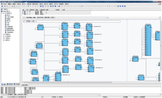
(2) The application configuration software contains a variety of special function blocks, and the program can be downloaded to the controller through the 485 communication interface. The programming language complies with the IEC61131-3 standard. It has a graphical editing tool with object-oriented programming.
(3) The controller has a built-in communication component. The RS-485 interface supports Modbus RTU mode and can communicate with the heating network monitoring center through a VPN broadband network.
(4) The controller can be operated on-site through the human-machine interface, data can be uploaded, and the thermal station can be completely unattended.
(5) It has good scalability and can be cascaded with multiple controllers to achieve control requirements.
(6) With remote maintenance function.
2. Heat exchange station control plan
1. Data collection: Create a database through the UWinTechPro control engineering application software, read the controller data, and display the operating parameters on the human-machine interface (touch screen); and upload it to the heating network monitoring center using GPRS wireless communication protocol or Ethernet to achieve remote control Monitoring; collected information includes but is not limited to the following:
Pressure (pressure difference): primary network supply and return water pressure, secondary network supply and return water pressure, pressure difference before and after the primary network water supply filter, pressure difference before and after the secondary network return water filter, secondary network outlet supply return water pressure difference.
Temperature: primary network water supply and return water temperature, secondary network water supply and return water temperature, outdoor temperature;
Valve position: Primary network electric regulating valve valve position
Liquid level: water tank liquid level
Variable frequency motor operating frequency: circulating pump inverter feedback frequency, water replenishing pump inverter feedback frequency
Operating status: circulation pump start, stop status, fault status; water replenishment pump start, stop status, fault status;
Alarm situation: Alarm can be issued according to the set situation.
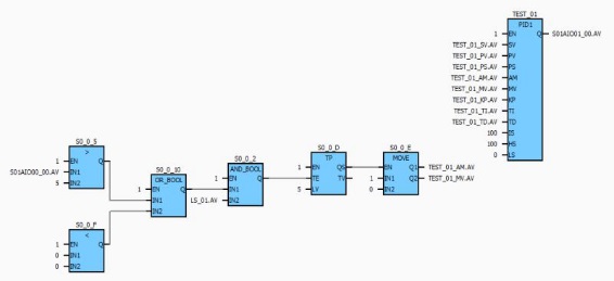
2. Temperature control loop:
The basic control strategy of the heat exchange station is to ensure constant temperature and pressure at the secondary water outlet, and to ensure constant temperature by controlling the primary water inlet electric regulating valve.
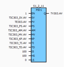
The preset temperature is used as the given value, the measured temperature is used as the feedback value, and the valve opening is output through PID calculation to ensure the constant temperature of the secondary water supply. The preset temperature is calculated based on the trade-off between the outdoor temperature and the value given by the heating network monitoring center. This set point can change with the changes in outdoor temperature and the given value of the heating station.
The controller controls the operation of the regulating valve through the analog output signal, and manual automatic control can be selected; in the automatic case, PID calculation is performed based on the secondary temperature supply feedback value and the set value, and the opening of the regulating valve is automatically and continuously controlled; in the manual case, Manually set the opening of the regulating valve.
3. Water replenishment control (water replenishment pump control)
The controller controls the start and stop of the water replenishing pump through the frequency converter and adjusts the speed of the water replenishing pump. Two modes of manual and automatic control can be selected. In the automatic case, start and stop judgments are made based on the secondary back pressure set value. If the secondary back pressure value is lower than the secondary back pressure value, the water replenishing pump will be started, and if the secondary back pressure value is higher than the secondary back pressure value, the water replenishing pump will be stopped. In the manual case, the water replenishing pump will be started and stopped manually. The frequency control of the water replenishing pump can also be controlled manually. In the automatic case, PID calculation is performed based on the difference between the secondary back pressure feedback value and the set value, and the frequency of the water replenishing pump is automatically and continuously controlled. In manual mode, manually modify the water replenishing pump frequency directly.
4. Circulation pump control
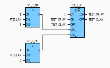
4.1 Pump start and stop control: There are two modes of manual and automatic control. In the automatic case, the start and stop determination is based on the secondary supply and return pressure difference. When it is lower than the set value, the circulation pump is started. When a failure occurs, the circulation pump is automatically stopped; in the manual case, the circulation pump is started and stopped manually.
4.2 Pump frequency control: Two modes of manual and automatic control can be selected. In the automatic case, PID calculation is performed based on the secondary supply and return pressure difference feedback value and the set value difference to automatically and continuously control the frequency of the circulating pump. In the manual case, manual Directly set the circulation pump frequency.
5. Drainage solenoid valve control
The drain solenoid valve can choose two modes of manual and automatic control. In manual mode, the solenoid valve can be opened and closed directly through the touch screen or upper monitoring system; in automatic mode, when the secondary supply pressure exceeds the safety set value, before the safety valve opens, Open the drain solenoid valve to drain water, reduce the pipeline pressure, and protect the safety of pipeline operation. When the secondary supply pressure returns to normal value, close the drain solenoid valve.
6. Water tank replenishment solenoid valve control
The water tank replenishment solenoid valve can be controlled in two modes: manual and automatic. In manual mode, the solenoid valve can be opened and closed directly through the touch screen or upper monitoring system; in automatic mode, when the liquid level in the water tank is lower than the safe set value, the water replenishment solenoid valve is opened to supply the water tank. To replenish water, when the liquid level in the water tank reaches the normal value, close the water replenishment solenoid valve.
7. System interlock protection
1) Pump and valve interlock: When the circulation pump stops running, in order to protect the equipment, the primary regulating valve is automatically closed to prevent the secondary high-temperature water from overheating and vaporizing and damaging the heat exchanger;
2) High and high limit of primary return temperature: Set the high and high limit of primary return temperature. When the primary return temperature exceeds the high and high limit, it will alarm and automatically close the primary regulating valve;
3) High limit of secondary temperature supply: Set the high limit of secondary temperature supply. When the secondary temperature supply exceeds the high limit, it will alarm and automatically stop the circulation pump to protect the end user;
4) High limit of secondary supply pressure: Set the high limit of secondary supply pressure. When the secondary supply pressure reaches the high limit, it will alarm and automatically stop the circulation pump operation to prevent pipeline overpressure;
5) Secondary back pressure low and low limits: Set the secondary back pressure low and low limits. When the secondary back pressure reaches the low limit, start the water replenishing pump to replenish water. When the secondary back pressure reaches the low and low limits, it will alarm and automatically stop the circulation pump to prevent the pipeline from running. Empty, the circulation pump is idling and damaged;
6) Water tank liquid level low limit: Set the water tank liquid level low and low limits. When the water tank liquid level reaches the low and low limits, it will alarm and stop the water replenishment pump to prevent the pipeline from emptying and the water replenishment pump from idling damage;
7) Power outage alarm: When the controller detects the power outage signal from the relay in front of the UPS, it will initiate a power outage alarm and close the primary regulating valve.
8. Communication function
Communication with touch screen: using Modbus protocol
Communication with heat meter: using Modbus protocol
Communication with the heating network monitoring center: using industrial Ethernet TCP/IP or GPRS wireless transmission protocol


