1. Project Overview
This project is an unattended automatic control system for heat exchange stations. The project includes six heat exchange stations including H area, I area, E area, north area, south area south, and south area north and one public station. The project aims to build an unattended automatic control system. The manned monitoring system optimizes production operation supervision methods, improves safety management levels, and enables centralized monitoring of the operating status of each heat exchange station equipment in the boiler room control room; the main operating parameters of the heat exchange station are centrally displayed in the boiler room control room to facilitate production technicians Quickly understand the operating status of the heat exchange station and analyze whether the equipment is operating in a reasonable state in order to optimize operating parameters; discover potential safety accidents in equipment operation as early as possible to reduce the incidence of accidents; reduce personnel investment and realize unmanned heat exchange stations Long-term duty reduces the frequency of station patrols and overall reduces labor costs.
1.1 The specific overview of each heat exchange station is as follows:
(1)H area heat exchange station:
The heating area of the heat exchange station in Zone H is 235318.59㎡. Among them, the high area is 111440.18㎡; the low area is 123878.41㎡. The ends are heated by radiators.
The main equipment in the high area of the station: 3 plate heat exchangers, 2 circulating water pumps, and 2 water supply pumps; the main equipment in the low area is: 3 plate heat exchangers, 2 circulating water pumps, and 2 water supply pumps; high and low areas Shared water treatment and other equipment.
(2) Area I heat exchange station:
The heating area of the heat exchange station in Zone I is 251177.9㎡. Among them, the high area is 126116.5㎡; the low area is 125061.4㎡. The ends are heated by radiators.
The main equipment in the high area of the station: 3 plate heat exchangers, 2 circulating water pumps, and 2 water supply pumps; the main equipment in the low area is: 3 plate heat exchangers, 2 circulating water pumps, and 2 water supply pumps; high and low areas Shared water treatment and other equipment.
(3) Area E heat exchange station
The heating area of the heat exchange station in Area E is 65290.35㎡. The ends are heated by radiators.
Main equipment in the station: 2 plate heat exchangers, 3 circulating water pumps, 2 water replenishing pumps, water treatment and other equipment.
(4) North District Heat Exchange Station
The heating area of the North District Exchange Station is 61,798.29 square meters, and the heating area will not be increased in the future. There is no domestic hot water, the heating system does not distinguish between high and low zones, and the eaves height is 12m.
Main equipment in the station: 2 plate heat exchangers, 3 circulating water pumps, 2 water replenishing pumps, water treatment and other equipment.
(5) South District North Heat Exchange Station
The heating area of the North Exchange Station in the South District is 109620.71㎡, and the commercial and other areas are 3661.87㎡. The heating area will not be increased in the future. There is no domestic hot water, and the heating system does not distinguish between high and low zones. The eaves height is 45m; the terminal heating is radiator heating.
Main equipment in the station: 2 plate heat exchangers, 3 circulating water pumps, 2 water replenishing pumps, water treatment and other equipment.
(6) South District South Heat Exchange Station
The heating area of the South Exchange Station in the South District is 125,404.8㎡, and the commercial and other areas are 1,727.02㎡. The heating area will not be increased in the future. There is no domestic hot water, the heating system does not distinguish between high and low zones, and the eaves height is 45m.
Main equipment in the station: 2 plate heat exchangers, 3 circulating water pumps, 2 water replenishing pumps, water treatment and other equipment.
1.2 The process flow of each heat exchange station is as follows:
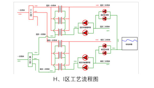
Process Description:
① The heat source of this station is provided by the boiler room. The water is supplied to the water distributor of the heat exchange station through the water supply main pipe for distribution, and supplied to the high and low zone plate heat exchangers respectively; after completing the heat exchange, it flows back to the water collector and returns to the boiler room through the return water main pipe.
② The secondary return water from the heat user is pressurized by the circulation pump and enters three sets of plate heat exchangers respectively. After heat exchange in the heat exchanger, it forms a secondary water supply, which is collected from the water supply side of the plate heat exchanger to the water supply tank. Pipes are distributed to heat users through the pipe network.
③ The fixed pressure point for water replenishment is located on the inlet main pipe of the circulation pump and is used to control the start and stop of the water replenishment pump and the release of overpressure water.
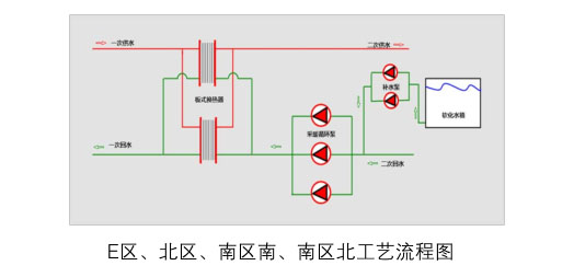
Process Description:
① The heat source of this station is provided by the Zhujiang Yijing boiler room. The water is supplied to two plate heat exchangers through the water supply main pipe; after completing the heat exchange, it is returned to the boiler room through the return water main pipe.
② The secondary return water from the heat user is pressurized by the circulation pump and enters two sets of plate heat exchangers respectively. After heat exchange in the heat exchanger, it forms a secondary water supply, which is collected from the water supply side of the plate heat exchanger to the main water supply pipe. The network is assigned to hot users.
③ The fixed pressure point for water replenishment is located on the inlet main pipe of the circulation pump and is used to control the start and stop of the water replenishment pump and the release of overpressure water.
Combining customer needs and actual project conditions, Hangzhou Youwen proposed a comprehensive all-in-one solution based on UW2100 industrial IoT eDCS control system hardware products and UWNTEK software products.
2. System design principles
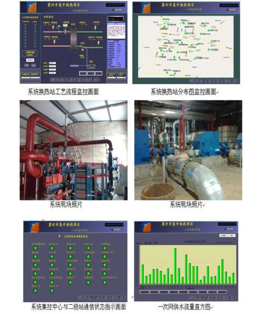
The heat exchange station unattended monitoring system based on UW2100eDCS system hardware and UWNTEK software platform integrates scheduling and monitoring. Its functions include human-machine interface, database management, remote data collection, remote control, alarms, trends and reports, etc., using various An advanced communication network that tracks and monitors the entire heating network pipelines, instruments, etc. not only allows dispatchers to fully grasp the heating status of the entire heating network pipelines, but also quickly and accurately reflects on-site fault alarm information to facilitate inspection and maintenance Timely maintenance by personnel not only saves a lot of manpower and material resources, but also greatly improves the modern management level of the heating network.
This design is based on the "centralized management, decentralized control" model and the idea of digital and informatized municipal engineering, focusing on the construction of the enterprise's "management and control integration" information system, and establishing an advanced, reliable, efficient, safe, integrated process control, A monitoring system that integrates monitoring and computer scheduling management and has good openness can complete the monitoring and automatic control of the entire heating process and all production equipment, achieving the goal of "unattended on-site and few people on duty at the main station".
3. Overall structure of the system
The entire system includes a new generation of perception control intelligent front-end that meets the application requirements of CPS cyber-physical systems and industrial Internet, a wide-area heterogeneous self-organizing industrial network, and a wide-area cloud service support environment for control system design, programming and control engineering.
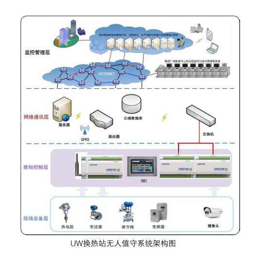
The system is based on the UW2100 controller to centrally collect on-site motor, valve, transmitter and other equipment information through standard 4~20mA, PT100, PT1000, level signal input, relay passive contact output, etc., and is based on wireless GSM The network centrally uploads data to the UWNTEK cloud platform to realize remote monitoring of wide-area information.
The on-site UW2100 controller communicates with the inverter based on the Modbus-RTU (RS-485) master station protocol to realize third-party device information collection, communication connection and control of multiple inverters; based on the Modbus-RTU (RS-485) slave station protocol Communicate with the touch screen to realize on-site monitoring of equipment information; at the same time, the UW500 distributed control system is used in the heat source boiler factory, and a central monitoring center is set up in the central control room to centrally monitor equipment information at various dispersed outlets.
The UWNTEK system software platform provides video integration functions, which can connect the standard video signals of cameras (Dahua, Hikvision) installed on-site to the system to realize remote monitoring of on-site real-time video signals; on this basis, the UWNTEK system software platform opens the standard HDMI interface , a large screen can be set up in the central control room, and key process processes can be connected to the central large screen display in the control room.
The system supports remote monitoring of mobile terminals (mobile phones, iPads, tablets, notebooks, etc.) in a wide area based on 2G, 3G, and 4G networks. Operation permissions can be divided according to security zones to ensure the security of the system.
4. System design plan
4.1 System Monitoring Center
The system monitoring center is located in the heat source boiler factory. The monitoring center mainly consists of several operator workstations (engineer workstations can be used concurrently with operator stations, the specific number depends on the design of the central control room), a large-screen display system, and an industrial Ethernet It consists of a switch, a graphics and report printer, a UPS power supply, etc.;
The computer in the monitoring center is required to be connected to the external network through wired or wireless means. The monitoring system uses a serverless star peer-to-peer structure. Based on the wireless GSM communication method and the UW cloud platform, a wide area network system is established for operator stations, engineer stations, various functional workstations and system peripherals. And based on the UW cloud server, the monitoring interface WEB is released to meet the needs of clients (computers, mobile phones, tablets, etc.) based on 2G, 3G, and 4G wide-area remote access.
4.1.1 System monitoring center function
1. Control of the water supply electric regulating valve on the primary side of the plate replacement
The opening of the electric regulating valve is controlled PID through the secondary side water supply temperature (the minimum opening of the electric regulating valve is determined taking into account the safety of boiler operation).
2. Monitoring of working status of plate heat exchanger
Temperature and pressure sensors are installed at the inlet and outlet of the primary and secondary side of the plate changer to monitor the working conditions of each plate changer.
3. Heating circulation water pump monitoring
A pressure sensor is installed on the inlet and outlet main pipe of the heating circulation pump to monitor the working status of the water pump and the system pressure.
4. Heating circulation pump and water replenishment pump inverter monitoring:
Remotely/locally monitor the start/stop status of the circulation pump; remotely monitor the working conditions of the inverter (output current, frequency, power, fault signal, etc.). The frequency converter is connected in series through the RS485 communication line to communicate with eDCS. eDCS can read various operating parameters, status and other signals of the frequency converter.
5. Secondary side supply and return water main pipe pressure and temperature monitoring
Temperature and pressure sensors are installed on the secondary side water supply main pipe; temperature sensors are installed on the return water main pipe. The pressure is taken from the pressure value of the circulation pump inlet main pipe, and the temperature and pressure conditions of the secondary side main supply and return water are remotely monitored.
6. Monitoring of pressure difference of decontamination device
Install a pressure difference transmitter on the secondary side return pipe decontamination device to remotely monitor the pressure difference between the inlet and outlet of the decontamination device to determine whether it is in normal working condition.
7. Liquid level monitoring of water replenishment tank
The softened water tank uses a pressure-type liquid level meter to transmit the liquid level signal to the eDCS controller in real time.
8. Water level monitoring in sump pits
A liquid level controller is added to the sump pit to monitor the water level in the sump pit; the sump pit is within the surveillance range of the camera to understand the sewage discharge situation in a timely manner.
4.1.2 Security protection and alarm
Use configuration software to establish a schematic diagram of the monitoring status of the heat exchange station, set alarm points at important locations, and use eye-catching red and green signs to indicate the fault status of the status points. While displaying the fault status, an audible alarm (voice prompt or siren sound, etc.) will be issued.
1. Low and high water tank level alarms
When the water tank level alarm is low, it means that the softened water in the water tank is about to be used up. If the water replenishing pump continues to run, the water pump may be damaged. Therefore, "water tank level is too low" is an alarm item for safe operation.
When the liquid level in the water tank is too high, it means there is a problem with the liquid level control device in the water tank. If you do not stop filling the water tank, the water in the water tank will be discharged from the overflow pipe, resulting in a waste of resources, and the water overflow pipe may not be discharged in time. As a result, water overflowed to other electrical control cabinets, causing safety accidents.
2. Low and high liquid level alarms in the sump
When a low liquid level alarm in the sump pit occurs, it means that the sewage in the sump pit has almost been drained. If the sewage pump continues to operate, it may malfunction due to waterless operation, or even a major accident in which the water pump is overheated and damaged.
When the liquid level in the sump pit is too high, it means that the sewage in the sump pit is not discharged in time. If you do not go to the site to inspect or take other sewage discharge measures, the water will overflow from the sump pit and overflow to the electric control cabinet, causing safety hazards. ACCIDENT.
3. Circulation pump failure alarm
By collecting signals through 485 communication, the fault status of the circulating pump can be discovered in time, which facilitates timely switching of the circulating pump, ensures heating quality, and eliminates faults in a timely manner.
4. Water replenishing pump failure alarm
The alarm items are the same as those of the circulating water pump.
5. Pressure difference alarm between the inlet and outlet of the decontamination device
When the pressure difference between the inlet and outlet of the decontamination device exceeds a certain value, it will seriously affect the circulating water flow of the system, which in turn affects the power consumption of the circulation pump. By detecting this parameter, the pressure difference of the decontamination device can be discovered in time. When the pressure difference exceeds the set value, the dirt remover must be cleaned.
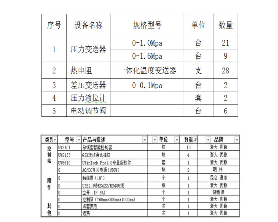
4.2 Unattended heat exchange station system hardware configuration plan, taking the unattended heat exchange station in Zone H as an example;
5. Plan description
This system is designed and implemented based on the UW2100 Industrial Internet of Things eDCS system hardware combined with UWWNTEK software. It establishes an advanced, efficient, high-quality and stable monitoring system that integrates process control, monitoring and computer scheduling management and has good openness to complete the entire heating process. Monitoring and automatic control of the process and all production equipment to achieve the following technical functions:
1) The data in the heat exchange station monitoring center is almost synchronized with the on-site data, reducing operating labor costs;
2) The monitoring system provides hardware and software environment support to solve the problem of heating network operation imbalance, achieve balanced operation of the heating network, and improve the heating effect.
3) It plays the role of energy saving and consumption reduction. The heat exchange station automatically adjusts the water supply temperature according to changes in outdoor temperature, thereby saving energy consumption to the greatest extent and improving the quality of heating service.
4) The phenomenon of steam theft and steam leakage is avoided. Due to the 24-hour online operation, the user's idea of steam theft is eliminated. Failures in on-site measurement can be discovered in the shortest time, and the failure time is recorded and filed. Avoid measurement losses.
5) Use the simulation system to perform hydraulic and thermal calculations on the heating network, and analyze the control operation of the heating network to achieve optimal operation of the heating network. Use fault diagnosis and energy loss analysis to understand the insulation and resistance losses of the pipe network, and the use efficiency of the equipment. Minimize the pipe loss of the heating network to achieve the most economical operation. Analyze the pipe network through comparison of historical data and real-time data.